I felt a need to add annunciating facility to my Home
Automation network, so I came up with this solution. The very basic idea is to
play an audio segment of choice over RS485 network. For this I made use of a
Serially Addressable MP3 playback module –WTM-SD. Audio for annunciation
purposes are stored in the On-board SD (up to 2 GB) card which is inserted in
this module, in mp3 format.
Features –
- ·
Single Supply Operation. 8 ~ 12V AC/DC
- ·
On-board stereo amplifier to drive the speaker
directly.
- ·
PWR ON
BUSY and ACTIVITY/RX Indicator LEDs
- ·
On-board volume Control POT for adjusting the
audio level.
- ·
On-board 5V regulator to supply regulated Power
to the Board.
- ·
Packet Protocol @ 9600 baud Rate.
Something about the MP3 Module –
The Model number of this module is WTM-SD and has four
control modes of operation - Standard mode(mp3 mode), Key mode, Parallel
mode, Serial mode. We
would be using the Serial mode for this project. This module safely operates on
5V DC, so there’s no need for a separate power source on the PCB. Standard
Serial protocol @ 9600 baud rate applies to control this module. A busy pin
Indicator is available , should you wish to use. I have used it , but yet have
not found a reason to apply it (make use of it). A total of 9 operating codes
are available to control various functions of this module and some, if not all,
have been used in this project.
The MP3 module has 3 LED , to indicate if the Module has Supply, a Busy Indicator - when the Module is playing audio and a SD Card Detect indicator to display when a inserted SD Card is recognized / detected by the Module itself. So when Powered on the PWR ON and the SD Card Indicator should light up.
Audio clips (files) are saved on the SD card in folders
with specific name like advert01, advert02 and so on. A total of 99 folders are
possible for use by the module, limited by the SD card capacity. Files have to
be in mp3 format only having file names like 001.mp3, 002.mp3 , so on. A total
of 999 files can be stored in each folder, again limited by the capacity of the
SD card , used. There’s no limit on the length/duration of the audio clip that
could be used. A must, the first folder (minimum) “advert01” must have a
configuration file , which decides the Control mode that is used by this
module. This is nothing but an ASCII file with the file name – cof.mp3 followed
by a configuration number. 1 – Standard Mode, 2 – Key Mode, 3 – Parallel Mode.
We use the standard mode. I don’t know why, but Serial Mode does not have a
number and can be addressed directly. But without this Config file in Standard
mode the module does not operate. Once this file is made and stored on the SD
card, it will show up as a audio file , because of its mp3 extension, which is
not a worry.
Operation –
This board operate on a similar line protocol followed by
its predecessor. A complete protocol summary is listed here.
PROTOCOL SUMMARY SHEET
|
ADDR
|
CMD
|
PARA
|
RESPONSE
|
XXX
|
XXX
|
XXX
|
PLAY
> FOLDER NO. + MSG NO.
|
XXX
|
100
|
0
|
STOP
PLAY
|
XXX
|
101
|
0
|
PAUSE
PLAY
|
XXX
|
102
|
0
|
START
PLAY FROM PAUSE
|
XXX
|
103
|
X
|
CHANGE
VOLUME (0-8)
|
XXX
|
104
|
0
|
QUERRY
VOL
|
XXX
|
105
|
0
|
QUERRY
FOLDER
|
XXX
|
106
|
XX
|
CHANGE
MAX. FOLDER - MAX. 99
|
XXX
|
107
|
0
|
QUERRY
BUSY PIN
|
XXX
|
110
|
XXX
|
PLAY
BACKGROUND AUDIO
|
XXX
|
111
|
0
|
PAUSE
BACKGROUND AUDIO PLAY
|
XXX
|
112
|
0
|
REPLAY
FROM PAUSE - BACKGROUND AUDIO
|
XXX
|
113
|
0
|
STOP
PLAY - BACKGROUND AUDIO
|
|
|
|
|
XXX
|
250
|
XXX
|
CHANGE NODE ADDRESS
|
XXX
|
251
|
0
|
Querry Product ID
|
XXX
|
252
|
0
|
Querry Product Firmware
|
XXX
|
253
|
123
|
RESET Board to Default Setting
|
123
|
254
|
255
|
Display Board Details
|
123
|
255
|
255
|
BOARD RESET/RE-START
|
|
|
|
|
PRODUCT ID:
|
228
|
MP3 ANNUNCIATOR MODULE
|
The Node/Slave address of this Board at start is 228. You
can change this if you wish like using appropriate command structure shown
above. Default Volume Level is 4 and Default Folder is 1 When a Query command
is issued , it generates a response which is sent back. Try and avoid it as it
could cause a clash on the network. These are used only during configuration of
this module , when this module is singly connected with a PC during
configuration.
For example if you wish to play a voice clip “002.mp3” in
folder “advert01” on the SD Card at address 228, then packet sent , should
be AT228001002<CR>
on the network. This information is shown if you want to create an
application to address this module on your own. To STOP PLAY, you issue a
packet AT228100000<CR> . Please
remember that the maximum Folders that can be allowed on the SD card are 99 and
each folder can have a maximum of 999 audio clips. I must admit that I have
not tried the Background Music option available on the MP3 Module, but I have
provided a provision for use, should any of you’ll plan to use. You could try
the options individually , by connecting this module separately to a PC and
issuing individual commands using a Terminal and the USB <> RS485 Bridge
PCB. .Remember the baud rate is @9600.
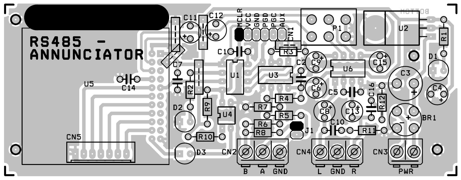
Power is applied at connector CN3 which should safely be
between 8 ~ 12V AC/DC. D1 is the Power On Indicator on the Board. LED D2 is an
Activity Indicator and blinks whenever a valid transmission is detected over
the Network. D3 LED is a Busy Signal indicator, which lights up when an audio
is being played / trigged. RS485 Network cable connects at connector marked CN2
on the PCB. Please remember to insert a jumper at J1 if this node is the last
component on your Network. This is the RS485 Termination link jumper. CN1 is a
ISP connector which is an optional component. Speakers are connected at
connector marked CN4 on the PCB. Any 8 ohm 1W speaker would do. If you want
more power, connect this output to your PA system. If assembling , remember
there are 5 jumpers on the PCB, assemble them first. CN5 marked on the PCB can
be omitted. Always remember to write down the present Node address on the White
Band available on the PCB. This will help you answer or address the module with
its address information.
Application –
I see a lot
of use of this module operated over RS485 network. One such idea was a Remote
Call Bell to be fitted in a PANTRY area having customized audio messages. This
application would involve 1 Slave unit , which is this PCB and many Masters ,
encoding required triggering option. Another Application would be a Nurse Call
Bell, where by a deserving patient gathers the attention of a Nurse / Maid with
Voice. When a Master with an RTC Clock is introduced over a RS485 system, it
can be programmed to annunciate different audio messages at a particular time
on different SLAVEs of this type. In a Fire/Security Alarm system for Remote Annunciation.
It can also be used in Annunciating purposes in Elevator systems. Keep thinking
and let me know……………
RS485 Aunnunciator Board
|
Sr.No.
|
Qty.
|
Ref.
|
Value
|
1
|
1
|
BR1
|
W04M
|
2
|
1
|
CN1
|
6 pin Bergh Pin (Optional)
|
3
|
2
|
CN2,CN4
|
3 PIN PBT CONNECTOR
|
4
|
1
|
CN3
|
2 PIN PBT CONNECTOR
|
5
|
1
|
CN5
|
7 PIN BERGH PIN (OPTIONAL)
|
6
|
7
|
C1,C2,C5,C7,C10,C14,C16
|
100N
|
7
|
1
|
C3
|
1000uF/25V
|
8
|
4
|
C4,C6,C9,C15
|
100uF/25V
|
9
|
2
|
C8,C13
|
220uF/25V
|
10
|
2
|
C11,C12
|
4u7F
|
11
|
3
|
D1,D2,D3
|
LED
|
12
|
1
|
J1
|
JUMPER + CLOSER
|
13
|
2
|
R3,R9
|
10K
|
14
|
1
|
P1
|
PCB MOUNTED DUAL GANG POT
|
15
|
3
|
R1,R2,R10
|
470E
|
16
|
2
|
R4,R7
|
1K
|
17
|
2
|
R5,R6
|
10E
|
18
|
1
|
R8
|
120E
|
19
|
2
|
R11,R12
|
4E7
|
20
|
1
|
U1
|
12F1840
|
21
|
1
|
U2
|
7805
|
22
|
1
|
U3
|
SN75176
|
23
|
1
|
U4
|
PC817
|
24
|
1
|
U5
|
WTM-SD + 2Gb SD Card
|
25
|
1
|
U6
|
TDA2822
|
26
|
3
|
|
8 PIN IC SOCKET
|
27
|
1
|
|
11x2 Row Female Connector for MP3
Module
|